
In May 2026, Autodesk introduced the Fusion MCP server. It lets you operate Autodesk Fusion directly from AI tools such as Claude or Cursor. Instead of writing code against the Fusion API, you describe what should be modeled, and the MCP server resolves the description into concrete operations such as Sketch, Extrude or Loft.
I tested the tool on two components from Swiss civil engineering: a road grate (BGS ALTO, figure AL670/AL676) and a hydrant upper section (Hinni OT6006). Both are classic components that appear in an infrastructure BIM model as part of a component library.
This article shows the setup, the individual iterations and my honest assessment. A spoiler up front: for detail-accurate workpieces the technology is not mature yet. For coarse BIM geometry, however, I already see a benefit.
What is Fusion MCP?
Model Context Protocol (MCP) is an open standard that gives AI models controlled access to external tools. Instead of relying on knowledge from training data, an AI can execute concrete actions inside a piece of software through an MCP server.
Fusion MCP applies this principle to Autodesk Fusion. The server exposes tools that let an AI create sketches, set parameters, extrude profiles, join components and build entire feature trees. The interaction happens through natural language. The geometry is created directly inside the Fusion document, so it stays editable, parametric and traceable.
Autodesk positions all of this as part of a broader MCP strategy. It aims to enable AI-assisted workflows in design and manufacturing without giving up control over the model. Every action remains visible in the feature tree and can be reworked manually.
Setup: Connecting Fusion MCP to Claude Desktop
The setup happens in two separate steps. First Claude Desktop, then Fusion. Both sides have to be active, otherwise no connection is established.
Requirements:
- Autodesk Fusion with a valid license and an up-to-date build
- Claude Desktop installed and connected to an account
Step 1: Install Autodesk Fusion in Claude Desktop
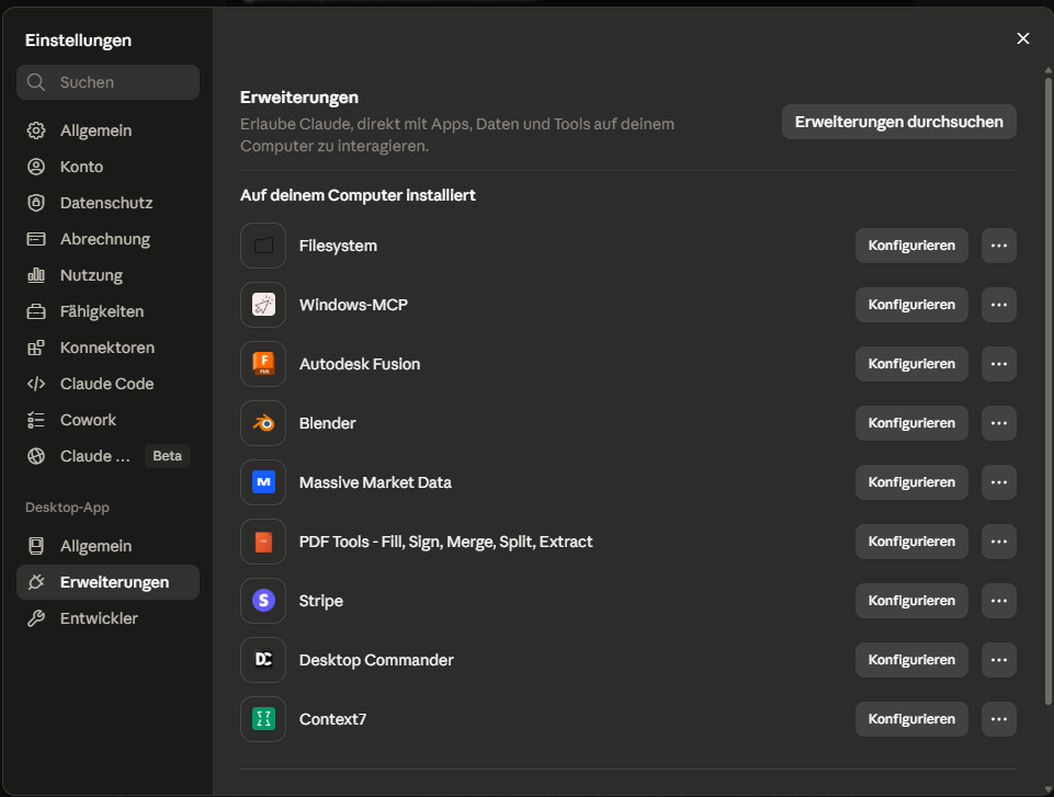
In Claude Desktop, open Settings → Extensions and install the "Autodesk Fusion" extension.
Step 2: Configure the extension
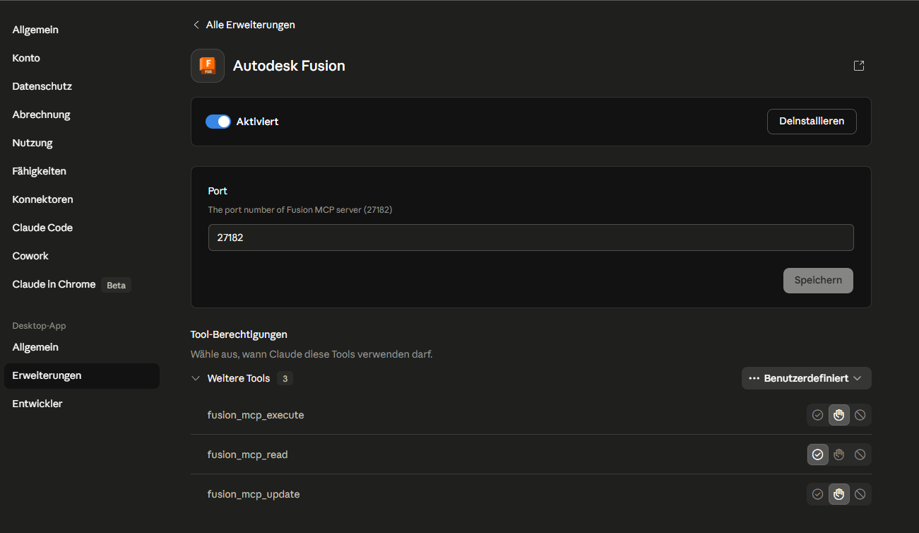
In the extension configuration, the port has to be set to 27182 (the default port of the Fusion MCP server). The three tools fusion_mcp_execute, fusion_mcp_read and fusion_mcp_update can each be set per action to "Ask", "Allow" or "Block". For getting started I recommend "Ask", so you can see what Claude actually intends to execute.
Step 3: Open the preferences in Fusion
On the Fusion side, the essential part is the checkbox in the settings dialog. Without this checkbox no MCP server runs, and Claude gets no connection. This is the single most important point of the whole setup.
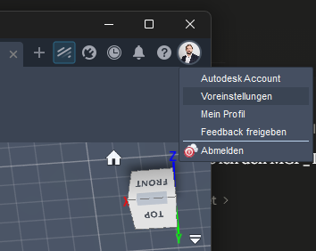
Click the profile picture in the top right and choose Preferences.
Step 4: Enable the API and switch on the Fusion MCP server
In the preferences under General → API you will find the Fusion MCP Server option. Tick the checkbox here. The port 27182 has to match the port from the Claude configuration.
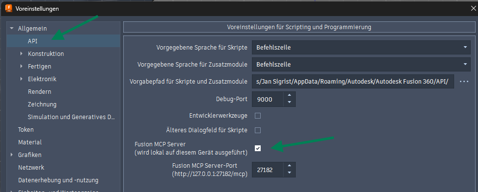
After saving, the server should be running at http://127.0.0.1:27182/mcp. Open an empty Fusion document and restart Claude Desktop. Claude accesses the document that is currently open. Without an active document the tools have no effect.
An additional step-by-step guide with screen recordings is shown in the video How to Connect Claude to Fusion 360 (MCP Setup Guide). If you want to take the community path, you will find suitable repositories on GitHub, for example Joe Spencer fusion-mcp-server.
Test case 1: BGS ALTO road grate
The first attempt targeted a classic BIM component: the BGS ALTO road grate, figure AL670S03 (class C250). The source is the figure sheet from BGS Bau Guss AG with the following dimensions:
- Frame (clear width): 435 x 340 mm
- Outer radius (R): 900 mm
- Height (H): 245 mm
- Cover (D): 522 x 375 mm
- Inlet area: 650 cm²
- Weight: 202 kg
I described the dimension sheets to Claude and asked it to model the component in Fusion. The result arrived over several iterations.
How big the leap between the first attempt and the final version is becomes clear in a direct comparison. Drag the slider:
The individual steps in detail, from the coarse envelope to the final component family:
Iteration 1: Coarse geometry
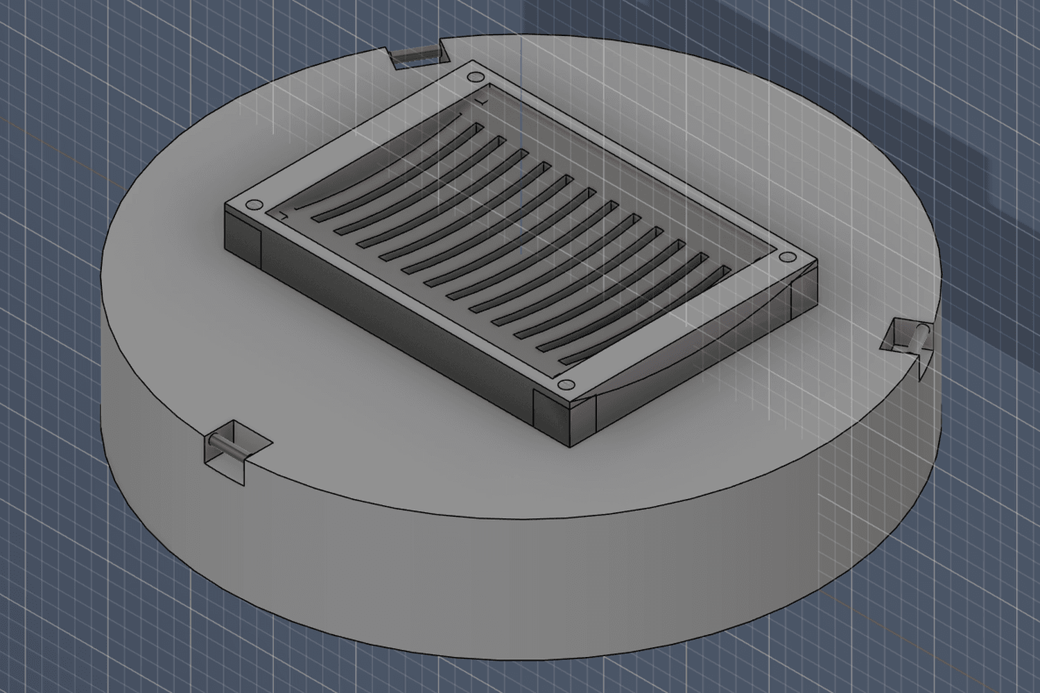
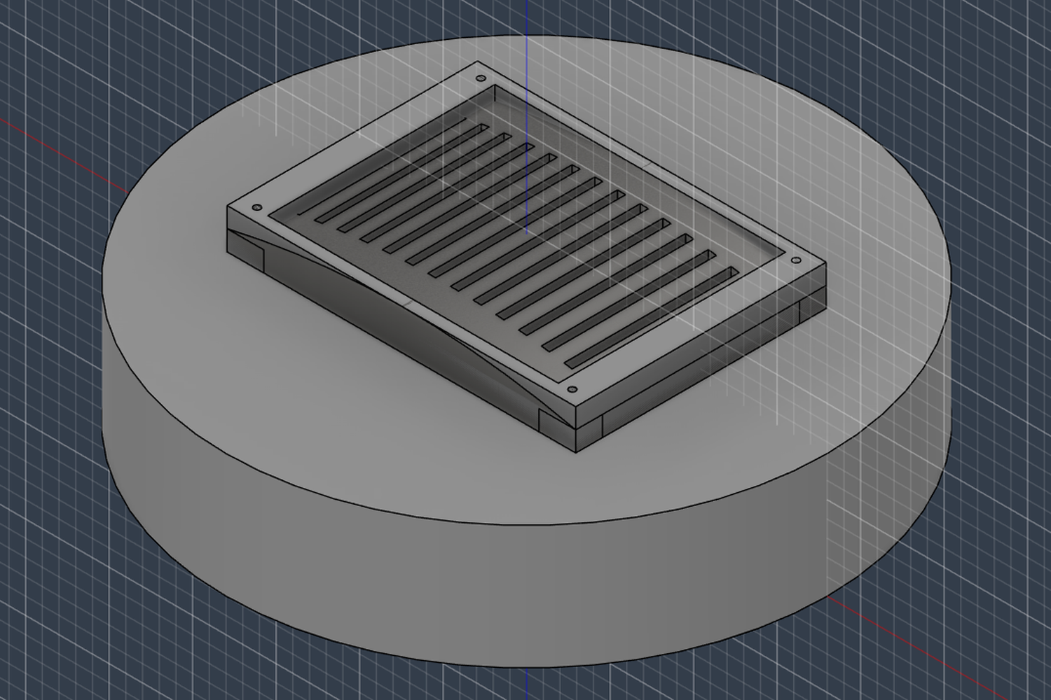
The first iteration shows the right basic concept. A round concrete part carries a rectangular cover with slots. The proportions are roughly correct, but the cover is curved in the wrong direction.
Assessment: Usable as a coarse envelope, but visually unsatisfying.
Iteration 2: Correct curvature
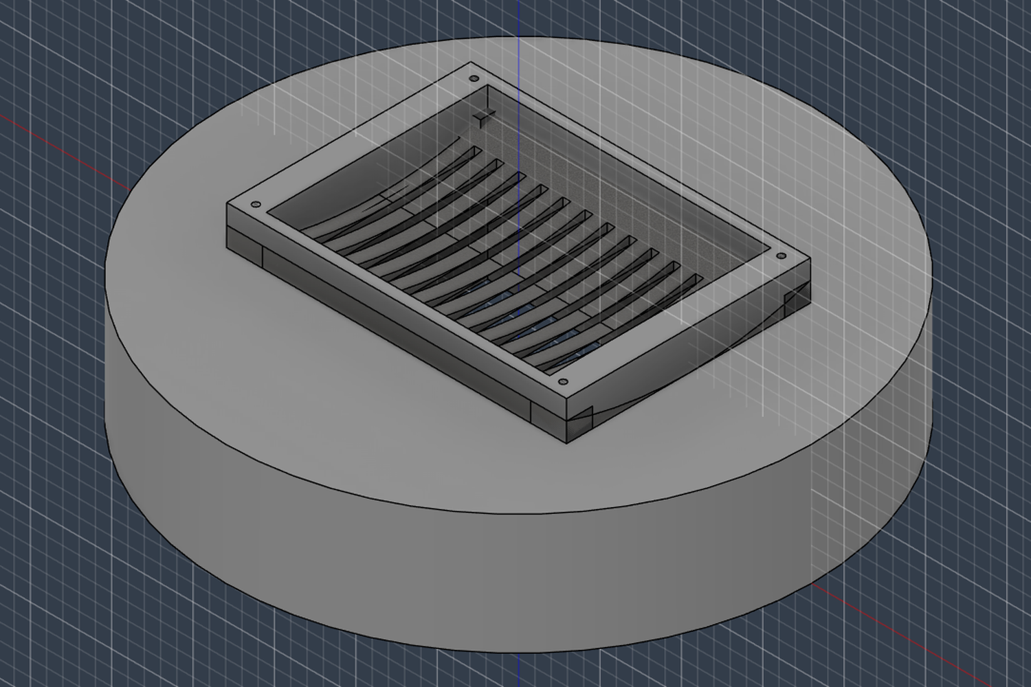
After a hint, Claude generated the cover with the correct curvature. This visibly comes closer to the real geometry. Unfortunately the plate is too deep and the frame was not curved along with it.
Assessment: A clear improvement. For a BIM model that conveys position and envelope, this would be sufficient.
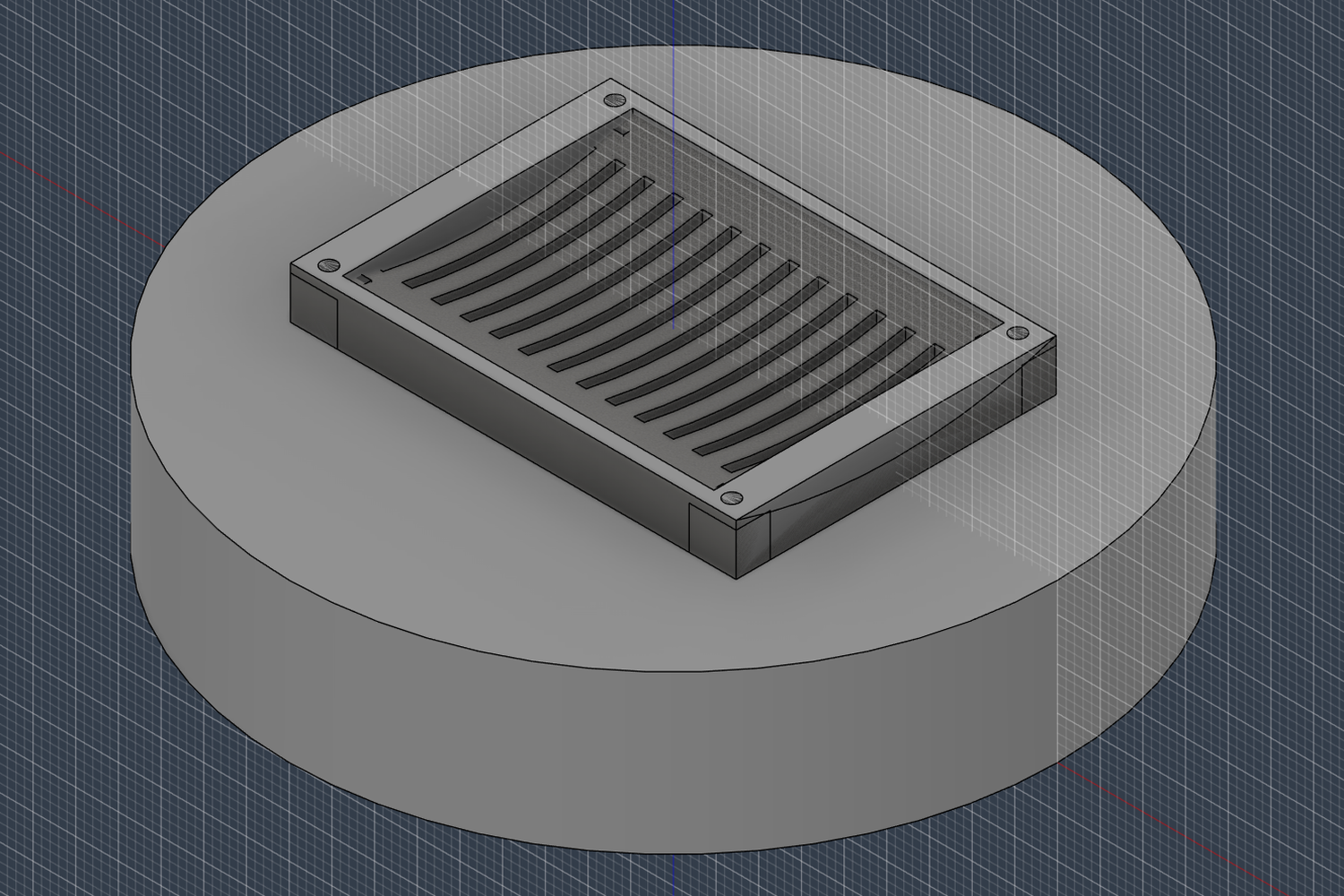
Iteration 3: Refined cover
The third iteration refines slots and cover. The frame is cleaner, the cover sits with four bolting points at the corners and was raised.
Assessment: Usable for a first dimensional placement, but still without the typical lifting brackets on the concrete edge.
Iteration 8: Final version
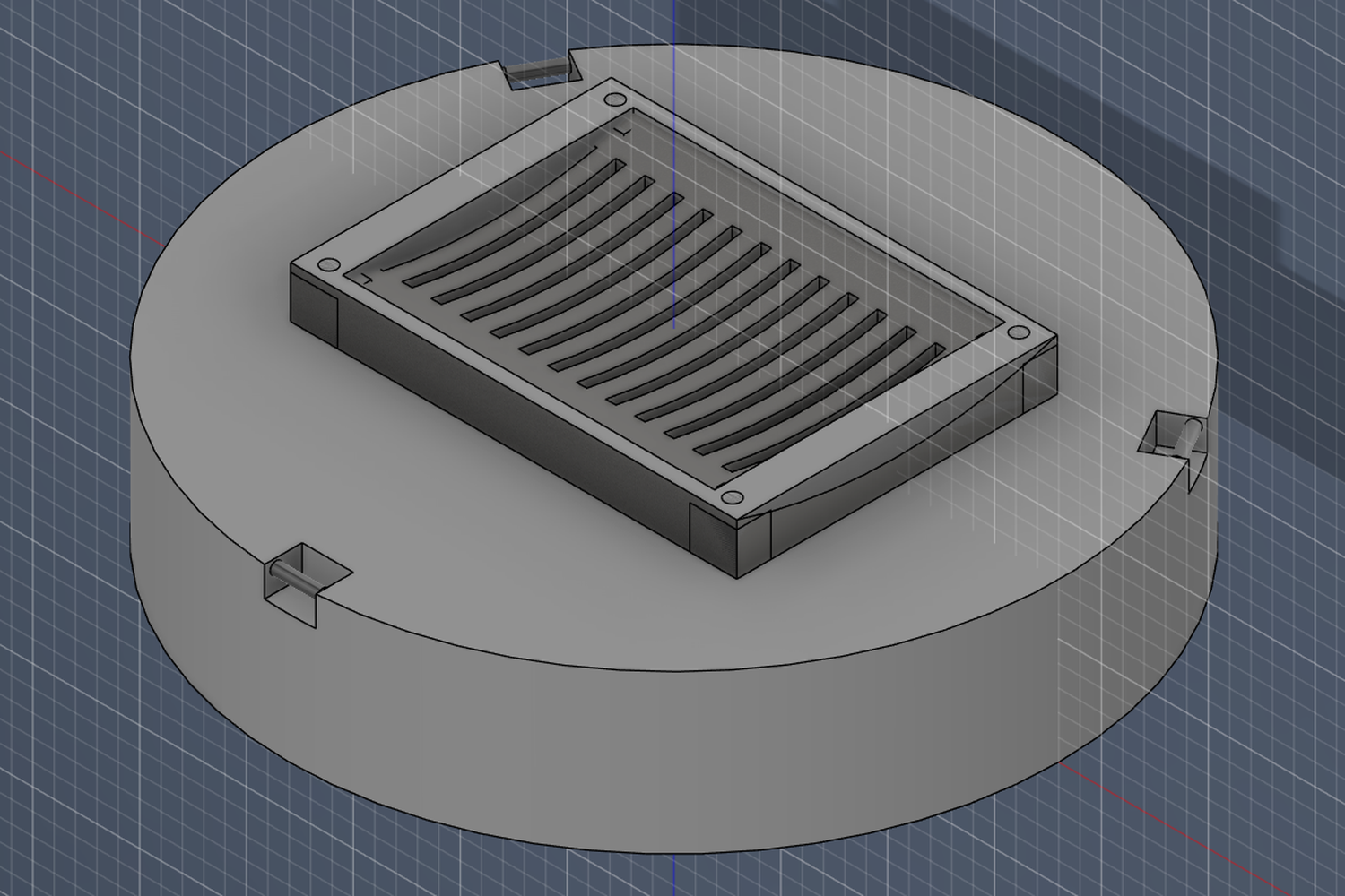
After six further iterations, the final version adds the lateral lifting brackets on the concrete edge. Four brackets, cleanly positioned, with the correct orientation. Two weaknesses remain visible: the cover sits centered in the concrete ring although the real ALTO insert is eccentric, and the frame stays straight although the cover itself is slightly curved.
Assessment: Sufficient as a component family for a dimensional placement in Civil 3D or Revit, provided the centered placement is manually corrected to an offset.
Test case 2: Hinni OT6006 hydrant
The second attempt was meant to be more ambitious: a hydrant upper section with a complex, curved shape. The source is the Hinni installation dimension sheet OT6006 360°.
The geometry includes:
- Riser pipe with an outer diameter of 140 mm
- Height 750 mm
- Bend at the upper end with a 30° outlet inclination
- Outlet length 240 mm
- Base with a diameter of 230 mm
- Depth dimension 260 mm
This is where things got genuinely tough.
Attempt 1: A blank without a bend
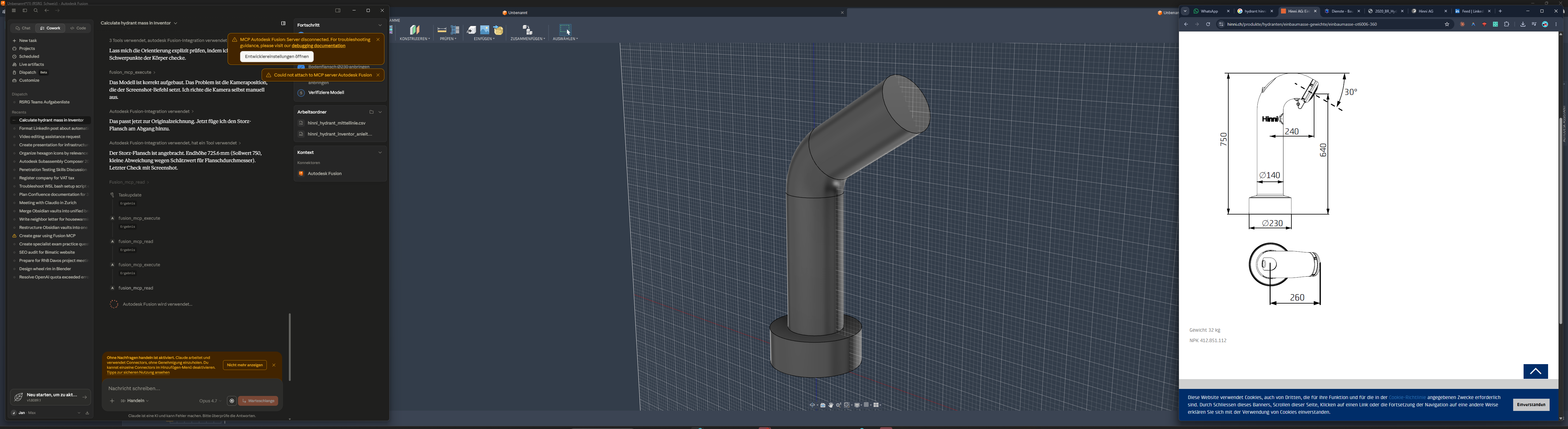
On the first try, a riser pipe with a kinked upper element was created. Instead of a smooth bend, Claude assembled two cylinders connected by an intermediate piece. The base was executed as a simple thickening at the foot. The proportions were correct, but the typical shape of a hydrant was not recognizable.
Assessment: it looks more like a piece of ventilation duct than a hydrant.
Attempt 2: No sketch, with self-derived dimensions
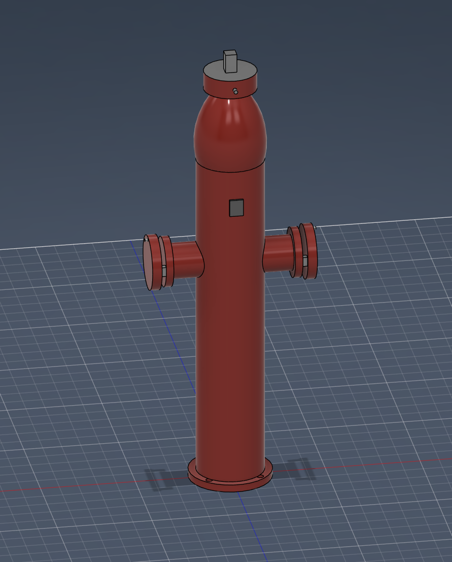
On the second try, I no longer showed Claude the Hinni sketch and only gave the instruction: "Create a typical Swiss hydrant". Claude then worked out the dimensions itself, or rather reconstructed them from its training knowledge.
The result moved even further away from the real shape: instead of a curved bend, a straight pipe with two laterally flanged nozzles was created. The final geometry had nothing in common with a Hinni hydrant anymore, and looks more like an American pillar hydrant or an industrial standpipe attachment.
Assessment: a failed attempt. Without a concrete dimension specification, Claude falls back on generic training knowledge, and that does not match Swiss hydrant practice.
Consequence: Modeled manually in Inventor
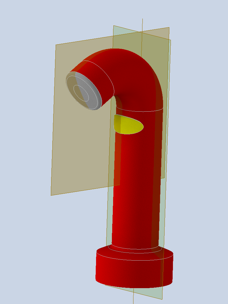
After the two failed attempts, I rebuilt the hydrant myself in Autodesk Inventor. With a sweep operation along a 3D curve, a loft at the transition to the bend and a simple lip at the base, the component was plausible in about 20 minutes.
Assessment: the manual construction was faster than iterating with Fusion MCP. For detailed, organic geometry the tool was simply not the right choice at this point in time.
What works and what does not
A few patterns can be derived from the two tests.
Already usable today:
- Simple, parametric geometry from Sketch and Extrude
- Components made of clearly directed volumes with few Boolean operations
- Iterative improvement over several prompt rounds, when the basic concept is correct
- Components where millimeter-level dimensional accuracy matters more than surface quality
Not yet reliable today:
- Complex lofts along 3D curves
- Organic, curved shapes with transitions
- Components where the order of operations decisively determines the topology
- Workpieces with a high level of detail (threads, undercuts, small radii)
- Constructions where components have to be placed eccentrically to one another
A recurring quirk: Claude tends to place components centered and symmetrically, even when the real component has an offset. The grate cover ended up centered in the concrete ring, although the ALTO grates are eccentric. Anyone reusing the model has to correct the placement by hand.
Put differently: Fusion MCP is suited today for geometry that an experienced CAD user could also draw in 10 minutes. For demanding constructions it is not yet a replacement, but at best a sketching aid.
Where the value for BIM already lies today
For detail-accurate workpieces I do not yet consider Fusion MCP equivalent for construction. It lacks the precision, the reliability across complex feature trees and the control over topology.
For coarse BIM geometry, however, I already see the value.
In an infrastructure BIM model we often need component libraries of road grates, manholes, hydrants, lamp posts, bollards or street furniture elements. These elements primarily fulfill three functions:
- Correct position in space (location and elevation)
- Correct envelope (clash detection against pipes, pavements, foundations)
- Recognizable identity (visual assignment during model review)
For all of this, a coarsely modeled geometry is enough. The final shop drawing comes from the manufacturer anyway, not from the BIM model.
This is exactly where Fusion MCP can already deliver a speed advantage today: instead of manually drawing every component or importing it from manufacturer catalogs, you describe the dimensions, let Claude generate a proposal and adjust the result manually. For a catalog with thirty components, that saves considerable time.
Outlook
The technology is at the very beginning. The Fusion MCP server has only been available for a few weeks, the selection of tools will expand, and the AI models will get better at spatial reasoning. Even today it is becoming clear that the combination of a parametric CAD engine and voice-driven operation will find a permanent place in everyday construction work.
My conclusion from the field test: not yet a replacement for CAD professionals today. But in the foreseeable future a practical accelerator for coarse geometry, placeholders and component families in infrastructure BIM. I will keep watching the tool and continue the tests as soon as the next versions become available.
Sources
- Autodesk Fusion Blog: Introducing the Fusion MCP, James Krenisky, 7 May 2026
- Autodesk AI: Autodesk MCP Servers overview
- YouTube: How to Connect Claude to Fusion 360 (MCP Setup Guide)
- GitHub: Joe Spencer, fusion-mcp-server
- BGS Bau Guss AG: Figure AL670/AL676, ALTO road grates
- Hinni AG: Installation dimensions and weight OT6006 360°
Video
A detailed video recording of the iterations is in preparation. Subscribe to the newsletter or follow Bimatic on LinkedIn to be notified.
Bimatic GmbH. From the ground up to automation.