
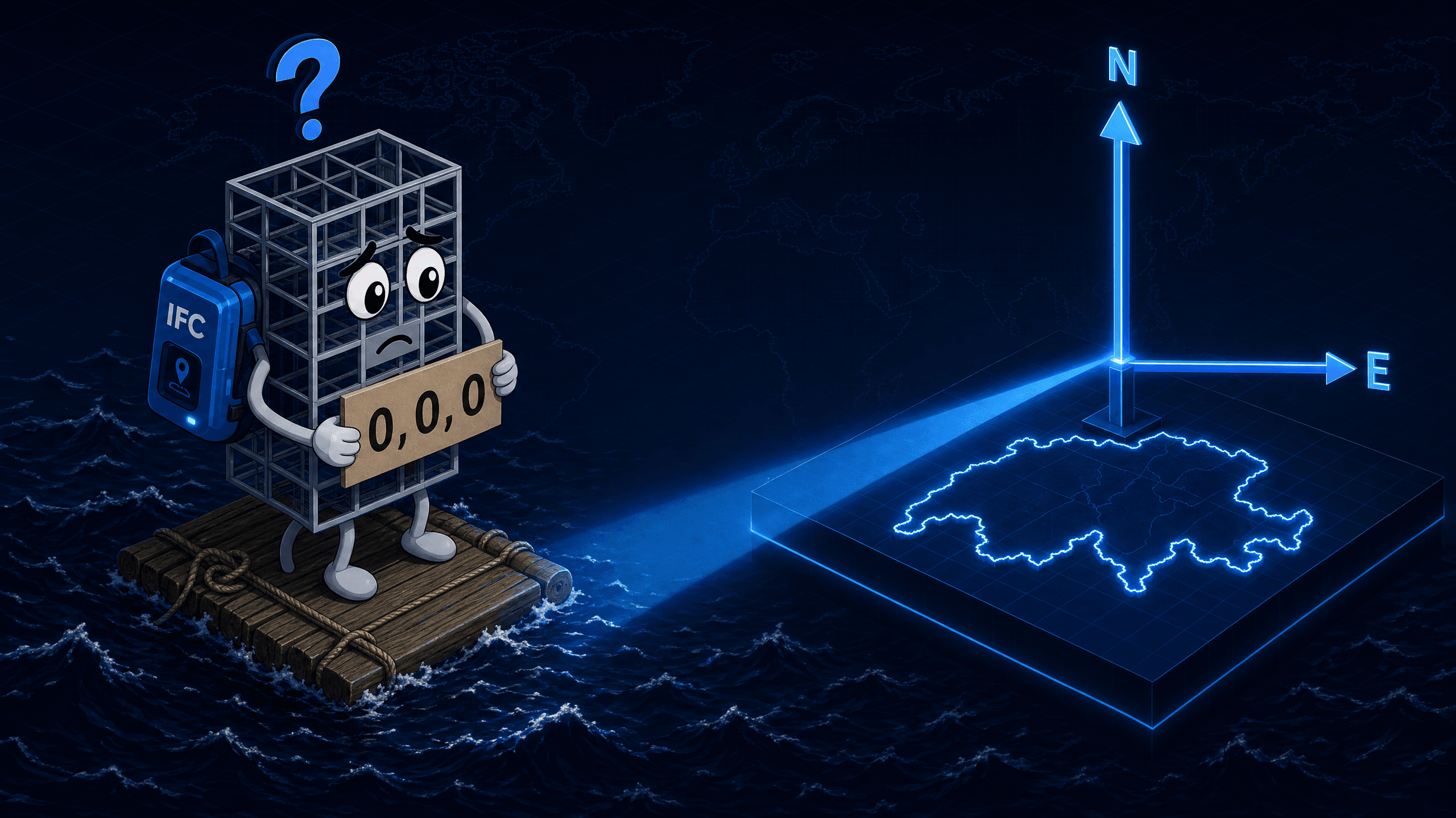
A BIM model lands 500 km from the correct location after import. Or it sits at the origin (0,0,0) instead of the Swiss national coordinate system. Or two tools read the same model and place it differently.
That is not an export error. That is a georeferencing problem.
The IFC standard has provided the entities and mechanisms to embed a model precisely into a geodetic reference system for years. The central question is: which entity is used correctly, and when?
This is where the LoGeoRef concept comes in. Five levels, from postal address to fully referenced coordinate transformation. Each level describes how much geospatial information is stored in an IFC file and through which entities it is carried.
That sounds theoretical. In practice, it determines whether your model lands in the client's coordinate system or nowhere at all.
What is LoGeoRef?
LoGeoRef stands for Level of Georeferencing. The concept was published in 2019 by Christian Clemen and Hendrik Görne (HTW Dresden) as an academic proposal to make the georeferencing quality of IFC files measurable. It is not an official buildingSMART or ISO standard, but a metric that has established itself as a de facto vocabulary in the field.
Clemen and Görne describe the purpose like this: LoGeoRef is meant to provide a common language that can be used in BIM processes to describe Exchange Requirements (ER), Employer's Information Requirements (EIR), and BIM Execution Plans (BEP).
The Five Levels at a Glance
LoGeoRef 10: Postal Address
The simplest form of georeferencing. The model contains an IfcPostalAddress assigned to an IfcSite or IfcBuilding. The address can include street, town, postal code, and country.
LoGeoRef 20: Geographic Coordinates on IfcSite
IfcSite carries the attributes RefLatitude, RefLongitude, and RefElevation. Coordinates are stored as a Compound Plane Angle (degrees, minutes, seconds, millionths of a second).
LoGeoRef 30: IfcLocalPlacement of the IfcSite
The position of the topmost spatial structure element (typically IfcSite) is stored directly in IfcLocalPlacement: X, Y, and Z coordinates plus axis directions via IfcAxis2Placement3D. Prerequisite: the element has no relative placement to another element (PlacementRelTo is empty).
LoGeoRef 40: WorldCoordinateSystem and TrueNorth
IfcGeometricRepresentationContext carries the WorldCoordinateSystem (WCS) and TrueNorth. The WCS can be used to rotate and translate the model coordinate system relative to global north.
LoGeoRef 50: IfcMapConversion and IfcProjectedCRS
This is the highest implemented level and the recommended method for full georeferencing in IFC. Two entities work together.
- • Name (e.g. CH1903+/LV95)
- • EPSG code (e.g. 2056)
- • Geodetic datum
- • Projection and length unit
- • Eastings, Northings, OrthogonalHeight
- • XAxisAbscissa = cos(angle)
- • XAxisOrdinate = sin(angle)
- • Optional Scale factor (default 1.0)
IfcMapConversion links the IfcGeometricRepresentationContext with the IfcProjectedCRS. The model itself keeps small, numerically stable coordinates, while the link to the national system is established exclusively through the conversion. LoGeoRef 50 is the prerequisite for proper BIM-GIS integration.
Extensions in IFC 4.3
With IFC 4.3 (more precisely: IFC4X3_ADD1) two additional entities have been introduced that can be used within LoGeoRef 50, particularly relevant for linear infrastructure.
When IfcRigidOperation is the Right Choice
In practice IfcRigidOperation is often the clean solution, not the inferior variant of IfcMapConversion. It explicitly communicates that only an offset is needed, with no rotation or scaling in between.
In any case the prerequisite is: the target system must additionally be defined via IfcProjectedCRS with a name and EPSG code. Without that, the offset is not machine-interpretable.
Comparison Table of the Levels
In the original paper Clemen and Görne also discuss a theoretical level LoGeoRef 60 with ground control points. It is not implemented and so far plays no role in practice.
The Most Common Mistakes in Practice
Redundant levels: LoGeoRef 40 and LoGeoRef 50 set at the same time, with geo information stored both in the WCS and in the IfcMapConversion. This produces conflicting placement information. Which mechanism wins depends on the importing tool and is not predictable.
TrueNorth conflict: TrueNorth set in IfcGeometricRepresentationContext and at the same time a rotation in IfcMapConversion. Both rotations stack. The result: the model is twisted by the difference angle.
Swapped axes: XAxisAbscissa and XAxisOrdinate in IfcMapConversion are swapped. Mathematically correct: XAxisAbscissa = cos(angle), XAxisOrdinate = sin(angle). Swapping them rotates the entire model by twice the angle.
Missing or wrong EPSG code: IfcProjectedCRS contains no or an invalid EPSG code. The target coordinate system can no longer be resolved by software. For Switzerland: EPSG 2056 (LV95).
IfcRigidOperation used incorrectly: IfcRigidOperation is the right entity when no rotation and no scaling against the target system are needed (see section above). It becomes problematic when an authoring tool uses it even though the model coordinate system is in fact rotated against grid north. With the IFC4.3 export from Autodesk Civil 3D this constellation is well known in practice and documented in several Autodesk support articles and forum threads. Since IfcRigidOperation per specification only carries translation in X, Y, and Z, a WCS rotation against grid north is lost on export, and the model lands shifted or twisted in downstream viewers. With Civil 3D 2026 (IFC 4.3 Extension 2026-23) Autodesk has improved the configuration, but an option to force IfcMapConversion with a rotation component is still missing. Anyone who needs to capture a rotation cleanly currently corrects the file afterwards, for example with ifcgref or IfcOpenShell.
Practical Recommendation for Swiss Infrastructure Projects
For long alignments, where scale distortions matter, using IfcMapConversionScaled with separate scale factors for X, Y, and Z within LoGeoRef 50 is worthwhile.
Sources
Bimatic GmbH, From the Ground Up to Automation. bimatic.ch